- 您现在的位置:买卖IC网 > Sheet目录343 > MIC4802YME (Micrel Inc)IC WHITE LED DVR 800MA 1CH 8SOIC
Micrel Inc.
Application Information
LED Current
MIC4802
Ultra Fast PWM? Dimming Interface
The MIC4802 supports a wide range of PWM control
signal frequencies from 200Hz to 500kHz. This
extremely wide range of control provides ultimate
flexibility for handheld applications using high frequency
PWM control signals.
WLED dimming is achieved by applying a pulse width
modulated (PWM) signal to the END pin. For PWM
frequencies between 200Hz – 10kHz the MIC4802
900
800
700
600
500
400
300
200
vs. PWM Duty Cycle
f PWM = 20kHz
f PWM = 100kHz
f PWM = 200kHz
supports a duty cycle range from 1% to 100%, as shown
in Figure 3. The MIC4802 incorporates an internal
shutdown delay to ensure that the internal control
circuitry remains active during PWM dimming. This
feature prevents the possibility of backlight flickering
100
0
0
20
f PWM = 500kHz
40 60 80
DUTY CYCLE (%)
100
when using low frequency PWM control signals. The
MIC4802 also supports Ultra Fast PWM? frequencies
from 20kHz to 500kHz. Due to input signal propagation
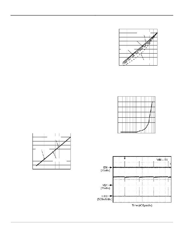
Figure 4. Channel Current Response to PWM Control
Signal Frequencies from 50kHz to 500kHz
delay, PWM frequencies above 20kHz have a non-linear
relationship between the duty cycle and the average
LED current, as shown in Figure 4 and 5. Figures 6
through 9 show the WLED current response when a
PWM signal is applied to the END pin (1) .
35
30
Minimum Duty Cycle
vs. Frequency
(1)
From the low I Q sleep mode higher PWM frequencies above 15kHz
25
require a logic high enable signal for 60 μ s to first enable the MIC4802
prior to PWM dimming .
LED Current
vs. PWM Duty Cycle
900
20
15
10
5
0
800
700
VIN = 5V
f PWM = 1kHz
100
1000 10000 100000
FREQUENCY (Hz)
1000000
600
500
400
300
200
100
0
f PWM = 5kHz
f PWM = 10kHz
Figure 5. Minimum Duty Cycle
for Varying PWM Frequency
0
20
40
60
80
100
DUTY CYCLE (%)
Figure 3. Average Current per LED Dimming
by Changing PWM Duty Cycle for PWM Frequencies
up to 20kHz
Figure 6. PWM Signal at 1% Duty Cycle (I avg = 8mA)
January 2011
8
M9999-013111-B
发布紧急采购,3分钟左右您将得到回复。
相关PDF资料
MIC4807BN
IC DRIVER 80V 8CH ADDRESS 18-DIP
MIC4811YMM
IC WHITE LED DVR HC 6CH 10MSOP
MIC4812YMME
IC WHITE LED DVR HC 6CH 10MSOP
MIC5011YN
IC DRIVER MOSF HI/LOW SIDE 8-DIP
MIC5013YN
IC DRIVER MOSFET HI/LO SIDE 8DIP
MIC5014YN
IC DRIVER MOSFET HI/LO SIDE 8DIP
MIC5016BWM
IC DRIVER MOSF DUAL HI/LO 16SOIC
MIC5018YM4 TR
IC DRIVER MOSFET HI SIDE SOT143
相关代理商/技术参数
MIC4802YME TR
功能描述:LED照明驱动器 800mA Single Channel WLED Driver w/ Ultrafast PWM Control
RoHS:否 制造商:STMicroelectronics 输入电压:11.5 V to 23 V 工作频率: 最大电源电流:1.7 mA 输出电流: 最大工作温度: 安装风格:SMD/SMT 封装 / 箱体:SO-16N
MIC4802YME-TR
功能描述:LED 驱动器 IC 1 输出 线性 PWM 调光 800mA 8-SOIC 制造商:microchip technology 系列:- 包装:剪切带(CT) 零件状态:停产 类型:线性 拓扑:- 内部开关:是 输出数:1 电压 - 供电(最低):3V 电压 -?供电(最高):5.5V 电压 - 输出:- 电流 - 输出/通道:800mA 频率:- 调光:PWM 应用:照明 工作温度:-40°C ~ 125°C (TJ) 安装类型:表面贴装 封装/外壳:8-SOIC(0.154",3.90mm 宽)裸焊盘 供应商器件封装:8-SOIC 标准包装:1
MIC4807
制造商:MICREL 制造商全称:Micrel Semiconductor 功能描述:80V 8-Channel Addressable Low-Side Driver
MIC4807BN
功能描述:IC DRIVER 80V 8CH ADDRESS 18-DIP RoHS:否 类别:集成电路 (IC) >> PMIC - MOSFET,电桥驱动器 - 外部开关 系列:- 标准包装:50 系列:- 配置:高端 输入类型:非反相 延迟时间:200ns 电流 - 峰:250mA 配置数:1 输出数:1 高端电压 - 最大(自引导启动):600V 电源电压:12 V ~ 20 V 工作温度:-40°C ~ 125°C 安装类型:通孔 封装/外壳:8-DIP(0.300",7.62mm) 供应商设备封装:8-DIP 包装:管件 其它名称:*IR2127
MIC4811
制造商:MICREL 制造商全称:Micrel Semiconductor 功能描述:High Current 6 Channel Linear WLED Driver with DAM? and Ultra Fast PWM? Control
MIC4811_1104
制造商:MICREL 制造商全称:Micrel Semiconductor 功能描述:High Current 6 Channel Linear WLED Driver with DAM? and Ultra Fast PWM? Control
MIC4811YMM
功能描述:LED照明驱动器 High Current Six Channel WLED Driver w/ DAM and Ultrafast PWM Control
RoHS:否 制造商:STMicroelectronics 输入电压:11.5 V to 23 V 工作频率: 最大电源电流:1.7 mA 输出电流: 最大工作温度: 安装风格:SMD/SMT 封装 / 箱体:SO-16N
MIC4811YMM TR
功能描述:LED照明驱动器 High Current Six Channel WLED Driver w/ DAM and Ultrafast PWM Control
RoHS:否 制造商:STMicroelectronics 输入电压:11.5 V to 23 V 工作频率: 最大电源电流:1.7 mA 输出电流: 最大工作温度: 安装风格:SMD/SMT 封装 / 箱体:SO-16N
